
WELDER & GRINDER (IDEAL BSO25)
IDEAL BSO25 Bandsaw Blade Welder & Grinder spare parts.
This unit is typically found on the Startrite V500, V900 & 316 industrial bandsaws.
-
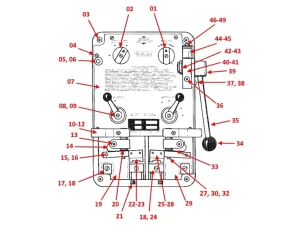
FRONT PANEL - IDEAL BSO25 BLADE WELDER (48)
-
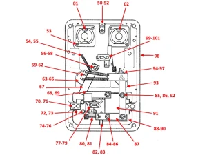
INTERNAL VIEW (REAR) – IDEAL BSO25 BLADE WELDER (54)
-
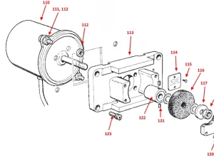
GRINDER UNIT for BSO25 BLADE WELDER (15)
BSO25 Blade Welder Operating Instructions
This welding unit is only suitable for butt-welding standard alloy wood & metal cutting bandsaw blades. It is not suitable for welding 2% – 3% tungsten alloyed or any H.S.S saw blades.
Before Attempting to operate the welder and grinder unit , become familiar with the controls and operating instructions
Butt-Welding Saw Blades
The process of butt-welding consists of clamping the saw blade between two sets of jaws, one set fixed and the other set moveable. The ends of the saw blade are heated by the passage of a heavy electric current and at the same time, they are forced together by a pre-determined amount under spring pressure. The welding unit enables the operator to re-join broken blades or to produce new blades from bulk coil strip as required.
Preparing the Saw Blade
Cut the saw blade to length using the blade shears. The shear is operated by moving the handle upwards. With fine pitch blades, the blade should be sheared in line with the tooth point in order to maintain a uniform tooth pitch after welding. It is important that the ends of the saw blade are sheared square in both planes and without burr. To achieve this the blade must be inserted in the shears with the teeth facing to the front. The back edge of the blade must seat against the back of the shears and against the alignment stop.
On wood cutting saw blades, the blade should be sheared mid-way between the tooth point, and the set of the teeth should be removed for a distance of 40mm both ends. (NOTE : The ‘set of the teeth’ refers to the angling of the teeth so that the tips protrude beyond the body of the saw blade).
When cutting all types of saw blades a small allowance should be made for the upsetting way ( the loss of length during welding, 1 – 3 mm according to type and gauge of blade. It may be found necessary to make trial welds ). Thoroughly clean both ends of the saw blade with emery for a distance of 40mm.
Welding
Make sure the clamping jaws of the welder are free from dirt and grease before using.
Set the welding current switch, upsetting pressure switch and upsetting way switch ( see General Layout illustration on page 1 ) according to the saw blade width. These settings are only a guide, and it may be necessary to adjust these according to circumstances. ( It may be found useful to make trial welds and keep a note of settings for future reference.
Place the prepared ends of the saw blade into position by means of the clamping screws, making sure that the two ends of the blade butt together at a point mid-way between the jaws. In order to avoid damage to both jaws and blade it is important that the blade teeth face forward against the front stops. Turn the upsetting way switch to the position marked ‘WELD’ and hold it there until the weld is finished ( welding takes approx. l second). The current is switched off automatically at the completion of the welding operation. After welding slacken off the clamping screws.
CAUTION : Sparks may fly during welding, therefore it is advisable to stand to one side and protect the face – WEAR EYE PROTECTION.
Annealing
A join produced by welding alone is brittle and would break after very little service. In order to overcome this the blade join must be annealed by a second operation. Set the upsetting way switch to the ‘ANNEAL’ position. Re-clamp the blade with the weld mid-way between the jaws. Hold the anneal switch in position until the weld is a dark cherry red. This process should be repeated a few seconds at a time letting the heat go slowly. Gradually reduce the length of time that the switch is held as the process proceeds.
Finishing
The excess weld flash must be removed by grinding, some care being taken to maintain a uniform blade thickness. The gullets of the teeth adjacent to the weld should be cleaned out as necessary. After the weld has been dressed in this fashion, anneal the joint to a pale blue colour
Possible Faults
If the weld has run too much or even shows holes, then the proportion of upsetting pressure to welding is incorrect. In such cases increase the upsetting pressure or decrease the welding current, it may be necessary to do both. If however, the upsetting pressure is too great and the welding current too small, the weld will have the appearance of loose layers.
NOI’E : Operating characteristics may vary slightly according to supply voltage, therefore it may be necessary to use an alternative setting in order to achieve optimum results.